- 您现在的位置:买卖IC网 > Sheet目录19096 > LD400600 (Red Lion Controls)COUNTER 6 DIGIT 4.0" 120VAC RED
�� �
�
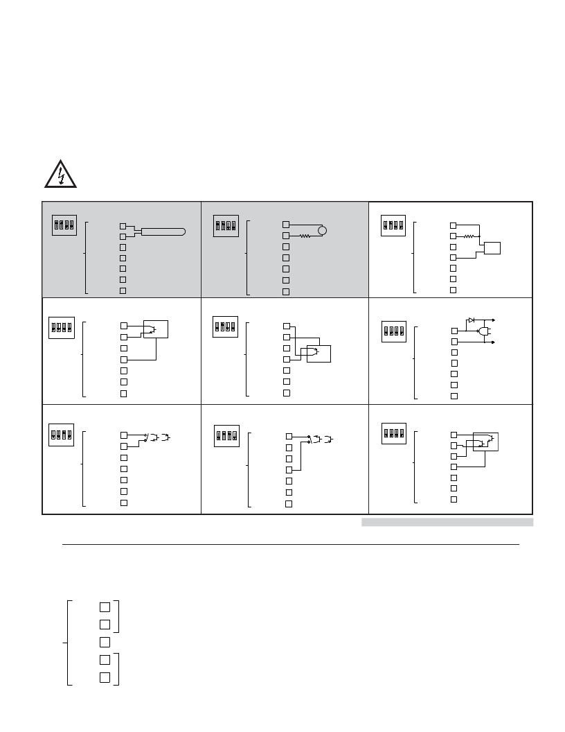
�3.4� INPUT� WIRING�
�The� Large� Display� has� two� signal� inputs,� A� and� B.� These� inputs� are� wired� to�
�terminal� block� TBB� located� inside� the� unit� on� the� right� side.�
�Terminal� 1:� Input� A�
�Terminal� 3:� Input� B�
�Terminal� 2:� Input� Common�
�All� other� models� are� non-programmable� and� provide� Count� with� Direction�
�Mode� only.� Input� A� accepts� the� count� signal,� while� Input� B� controls� the� count�
�direction� (up/down).�
�Input� B� can� also� be� used� to� adjust� the� LED� display� intensity� by� setting� DIP�
�Switch� 8� to� the� ON� position� (See� Section� 2.0,� Setting� the� DIP� Switches).� For�
�programmable� models,� this� only� applies� in� Count� with� Direction� mode.�
�Programmable� models� LD2006P0� and� LD4006P0� provide� a� choice� of� eight�
�different� Count� Modes.� The� Count� Mode� selected� determines� the� action� of�
�Inputs� A� and� B.� Section� 5.1,� Input� Setup� Parameters,� provides� details� on� count�
�mode� selection� and� input� action.�
�CAUTION� :� User� common� is� NOT� isolated� from� input� common.� In� order� to� preserve� the� safety� of� the� meter� application,� the� DC� common� must� be� suitably�
�isolated� from� hazardous� live� earth� referenced� voltage;� or� input� common� must� be� at� protective� earth� ground� potential.� If� not,� hazardous� voltage� may�
�be� present� at� the� User� Input� and� Input� Common� terminals.� Appropriate� considerations� must� then� be� given� to� the� potential� of� the� input� common� with�
�respect� to� earth� ground.�
�Magnetic� Pickup�
�AC� Inputs� From� Tach� Generators,� Etc.�
�Two� Wire� Proximity,� Current� Source�
�ON�
�Input� A�
�ON�
�Input� A�
�ON�
�Input� A�
�1� 2� 3� 4�
�INP� A� 1�
�INP� COMM� 2�
�MAGNETIC� PICKUP�
�1� 2� 3� 4�
�INP� A� 1�
�INP� COMM� 2�
�Resistor� to�
�AC�
�1� 2� 3� 4�
�INP� A� 1�
�INP� COMM� 2�
�2.2� k� Ω�
�TBB�
�INP� B� 3�
�+EXC� 4�
�TBB�
�INP� B� 3�
�+EXC� 4�
�limit� current�
�to� 2.5� mA� MAX.�
�TBB�
�INP� B� 3�
�+EXC� 4�
�RESET/USER� 5�
�COMM� 6�
�COMM� 7�
�RESET/USER� 5�
�COMM� 6�
�COMM� 7�
�RESET/USER� 5�
�COMM� 6�
�COMM� 7�
�Current� Sinking� Output�
�ON�
�Input� A�
�Current� Sourcing� Output�
�ON�
�Input� A�
�Interfacing� With� TTL�
�Input� A�
�+5� V�
�1� 2� 3� 4�
�TBB�
�INP� A� 1�
�INP� COMM� 2�
�INP� B� 3�
�+EXC� 4�
�NPN�
�O.C.�
�1� 2� 3� 4�
�TBB�
�INP� A� 1�
�INP� COMM� 2�
�INP� B� 3�
�+EXC� 4�
�PNP�
�O.C.�
�ON�
�1� 2� 3� 4�
�TBB�
�INP� A� 1�
�INP� COMM� 2�
�INP� B� 3�
�+EXC� 4�
�COMMON�
�RESET/USER� 5�
�COMM� 6�
�COMM� 7�
�Switch or Isolated Transistor; Current Sink�
�RESET/USER� 5�
�COMM� 6�
�COMM� 7�
�Switch or Isolated Transistor; Current Source�
�RESET/USER� 5�
�COMM� 6�
�COMM� 7�
�Current� Sink� Output;� Quad/Direction�
�ON�
�Input� A�
�ON�
�Input� A�
�ON�
�1� 2� 3� 4�
�TBB�
�INP� A� 1�
�INP� COMM� 2�
�INP� B� 3�
�+EXC� 4�
�1� 2� 3� 4�
�TBB�
�INP� A� 1�
�INP� COMM� 2�
�INP� B� 3�
�+EXC� 4�
�1� 2� 3� 4�
�TBB�
�INP� A� 1�
�INP� COMM� 2�
�INP� B� 3�
�+EXC� 4�
�RESET/USER� 5�
�COMM� 6�
�COMM� 7�
�*� Switch� position� is� application� dependent.�
�RESET/USER� 5�
�COMM� 6�
�COMM� 7�
�RESET/USER� 5�
�COMM� 6�
�COMM� 7�
�LD2006P0� and� LD4006P0� only.�
�Shaded areas not recommended for counting applications.�
�3.5� SERIAL� WIRING�
�The� serial� connections� are� made� via� terminal� block� TBD� located� inside� the�
�unit� on� the� left� side� for� the� LD2� and� on� the� right� side� for� the� LD4.�
�TXD� 1�
�232�
�RXD� 2�
�TBD�
�COMM� 3�
�A� 4�
�485�
�B� 5�
�5�
�发布紧急采购,3分钟左右您将得到回复。
相关PDF资料
5680F3;5
LED T1 DUAL AMBER/GREEN RA PCB
5680F7;1
LED T1 DUAL YLW/RED RA PCB
LD400400
COUNTER 4 DIGIT 4.0" 120VAC RED
ASD3-27.000MHZ-ECT
OSCILLATOR 27.000 MHZ 1.8V SMD
LD2006P0
COUNTER 6 DIGIT DUAL 2.25" RED
LD200600
COUNTER 6 DIGIT 2.25" 120VAC RED
ASD1-33.000MHZ-ECT
OSCILLATOR 33.000 MHZ 3.0V SMD
LD200400
COUNTER 4 DIGIT 2.25" 120VAC RED
相关代理商/技术参数
LD4006P0
功能描述:COUNTER 6 DIGIT DUAL 4.0" RED RoHS:是 类别:工业控制,仪表 >> 计数器 系列:LD 其它有关文件:Declaration of Conformity 标准包装:1 系列:99766 计数速率:25Hz 数字/字母数:5 输入类型:机电式脉冲 输出类型:- 电源电压:24V 显示器类型:十进制拨轮
LD400-AC
制造商:MRV 制造商全称:MRV 功能描述:LambdaDriver Chassis - DWDM/CWDM Platform
LD400-DC
制造商:MRV 制造商全称:MRV 功能描述:LambdaDriver Chassis - DWDM/CWDM Platform
LD400L-2AC
制造商:MRV 制造商全称:MRV 功能描述:LambdaDriver Chassis - DWDM/CWDM Platform
LD400L-2DC
制造商:MRV 制造商全称:MRV 功能描述:LambdaDriver Chassis - DWDM/CWDM Platform
LD400L-AC
制造商:MRV 制造商全称:MRV 功能描述:LambdaDriver Chassis - DWDM/CWDM Platform
LD400L-DC
制造商:MRV 制造商全称:MRV 功能描述:LambdaDriver Chassis - DWDM/CWDM Platform
LD400RN-DC
制造商:MRV 制造商全称:MRV 功能描述:LambdaDriver Chassis - DWDM/CWDM Platform